TM 9-6115-604-34
NAVFAC P8-633-34
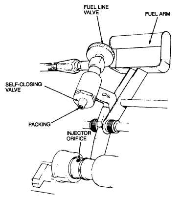
Figure 6-28. Fuel Arm and Supply Valve
(18)
The injector flow per 1000 strokes should be 284.5 to 286.5 cc.
(19) It the injector over 286.5 cc, install a metering orifice as follows:
CAUTION
To avoid damage to the test stand, do not leave the injector clamped more than 1 minute after
stopping the main drive. Do not, however, unclamp the injector until the main drive motor has
stopped.
(a)
Raise the fuel arm (21, Figure 6-20), wait until the main drive motor stops, then release the damping
control the guard (20) and raise the guard (23).
(b)
Remove the orifice (10, Figure 6-21) from the adapter (17) using a 5/64 inch hex head driver.
Remove and discard the orifice plug gasket (11).
NOTE
Orifices are available in sizes 0.029, 0.030, 0.031, and 0.032.
(c)
Select a smaller orifice (10), and install a new orifice gasket (11 ) and the smaller orifice in the
adapter (17). Tighten the orifice to 8 to 10 pound-inches (0.90 to 1.13 newton-meters).
(d)
Recheck the injector flow in accordance with steps (14) through (17), above.
6-53