TM 9-6115-604-34
NAVFAC P-8-633-34
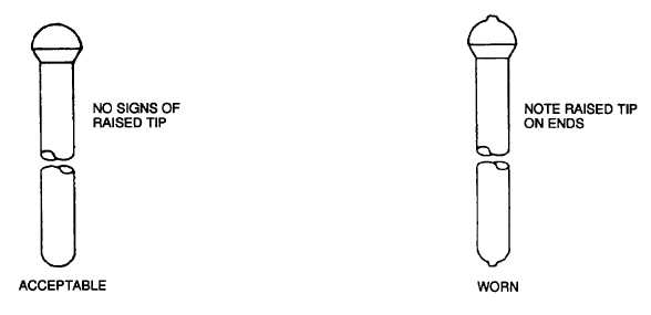
Figure 6-22. Plunger Link Wear
g.
Replace the check ball (13) if it shows any signs of wear or deformation when examined under four power
magnification.
h.
Inspect the packing ring grooves in the adapter (17) for defects which would prevent proper sealing. Replace
defective adapters.
i.
Use a four power magnifying glass to check the orifice (10) for burrs or an elongated hole. If the orifice shows
signs of damage, replace it with a new one of the same size.
NOTE
Orifices are available in 0.029, 0.030, 0.031, and 0.032 inch (0.74, 0.76, 0.79, and 0.81 mm).
6-16. FUEL INJECTOR ASSEMBLY.
a.
Install the check ball (13, Figure 6-21) and, if removed, new spiral pins (14) into the barrel (15).
b.
Holding the barrel (15) upright to prevent loss of the check ball (13), install the adapter (17) on the barrel.
c.
Turn the assembled barrel (15) and adapter (17) upside down, and place the cup (16) on the barrel.
d.
Lubricate the threads of the injector retainer (12) with 20 or 30 weight motor oil MIL-L-9000, and install it on the
assembled cup (16), barrel (15), and adapter (17). Tighten the retainer finger tight e. Dip the plunger (3) in clean
injector test oil, and install it in the assembled injector. Do not install the spring (4) at this time.
f.
Install injector cup wrench ST-995 on the retainer (12), and install the injector and wrench in assembly stand ST-
1 298.
g.
Activate the air cylinder on ST-1 298, and adjust the pressure to 70 psi (483 kPa), to align the cup (16) and
plunger (3).
h.
Using a torque wrench in conjunction with 1-1/4 inch crow-foot wrench, tighten the retainer to 50 pound-feet (68
newton-meters).
6-46


