ARMY TM 9-6115-604-12
NAVY NAVFAC P-8-633-12
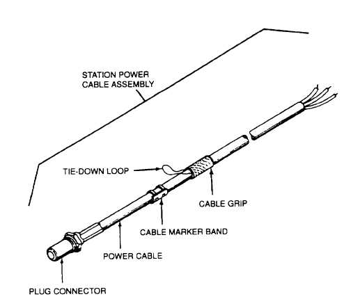
Figure 3-8. Cable Assemblies (Sheet 1 of 2)
c.
Maintenance of Outgoing Power Cable Assemblies. (Load Cables L0, L1, L2, and L3.)
(1) Inspect. See Figure 3-9. Perform visual inspection on each outgoing power cable assembly as follows:
(a) Check elbow connectors for cracks, deformities, and other damage Check that the conductor sleeve
inside each elbow connector is clean and free from obstructions and damage.
(b) Lay out cables and inspect insulation for cuts, cracks, ruptures, and other possible damage.
(c) Check that the shielding braid (wire) on each power cable is secured at the base of the elbow connector.
Also check that the shield grounding wire is secured at the other side of the shield wire mounting screw.
(d) Inspect output terminal lugs on each cable Check that the lugs are securely attached to the cables and
free from corrosion and damage. Also check that the other end of the cable shielding wire is firmly
attached to the cable.
(e) Check that the outgoing power marker bands on each cable (L0, L1, L2, and L3) are clearly legible and
securely attached.
(f)
Check that the cable grips are securely fastened to the cable insulation sleeves Check that the tie-down
loop on each cable grip is functional.
(2) Replace. Replace defective outgoing power cable assembly. Refer to the next higher level of maintenance
for repair.
3-32