ARMY TM 9-6115-464-34
AIR FORCE TO 35C2-3-445-2
NAVY NAVFAC P-8-624-34
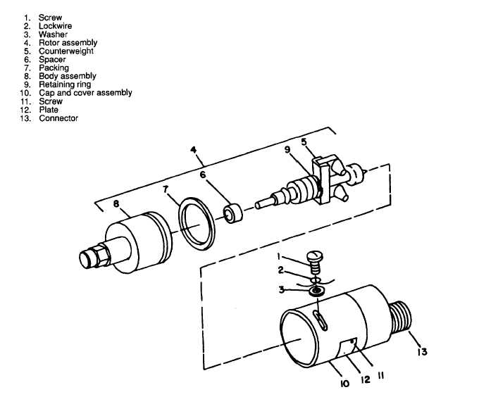
Figure 3-15. Speed Switch, Exploded View (Mechanical Switch) (Sheet 2 of 2)
NOTE
To obtain the required performance characteristics during tests (3) through (6),
adjustments can be made. By loosening screws (1, figure 3-15, sheet 2) and rotating
the cap and cover assembly relative to the body assembly, the trip points of all those
elements can be raised or lowered. In addition, the trip speed of each individual
element can be raised or lowered by removing access screws as shown in figure 3-16
sheet 2 and turning appropriate set screw located beneath cover screws with a 1/16
inch allen wrench.
I. Installation. Refer to Operator and Unit Maintenance Manual and install speed switch in reverse order of
removal.
3-36