ARMY TM 9-6115-464-34
AIR FORCE 35C2-3-445-2
NAVY NAVFAC P-8-624-34
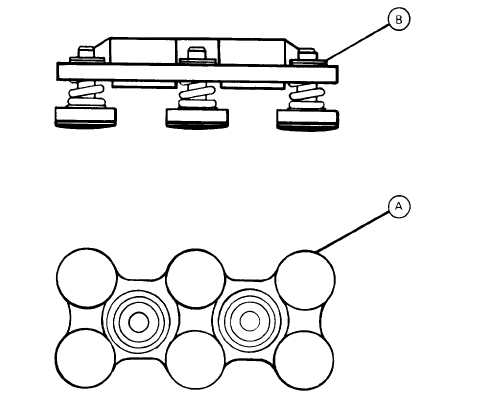
Figure 3-103. Main Contact Preload Check Points
(16) Check preload of each contact as follows: (See figure 3-103.)
NOTE
(Type A)
Preload is checked by the initial breakaway of retaining ring (point (B)).
(a) Using a force gauge, check each individual contact at its edge (point (A)). Preload should be 1.5 to
2.5 pounds.
(b) If preload is not as specified, add or subtract shims (26, 29, and 30, figure 3-100).
(17)
(18)
Install actuator and connector assembly (45, figure 3-1 00) onto main base (46) and secure with
bushing (44), Iockwashers (43) and screws (42).
Install main contact assembly (23) and secure with Iockwashers (22) and nuts (21). Adjust contact
over travel as follows: (See figure 3–104.)
(a) Attach an ohmmeter to terminals A1-A2 and C1-C2.
(b) Insert a 0.035 inch feeler gauge into core gap (point A).
(c) Energize coil by applying 24 Vdc across connector pins A and B (See figure 3-105).
(d) Adjust carrier bushing at point (B) (Figure 3-104) until continuity is indicated at terminals A1-A2
and C1-C2.
(e) Secure adjustment by tightening nuts (1).
(f) Recheck for continuity at a clearance of 0.035 inch and for open circuit at 0.040 inch.
(19) Adjust economizing switch as follows: (See figure 3-104).
3-222