T M 5 - 6 1 1 5 - 5 8 4 - 34
NAVFAC P-8-622-34
T O - 3 5 C 2 - 3 - 4 5 6 - 2
TM-0568C-34
C. Main Generator. Exciter field voltage and current
versus load, see the following:
Exciter
Percent of Rated Load
1O-.8PF, 120 V
Volts
Amps
0
17.8
0.96
25
21.7
0.56
50
25.5
0.66
75
29.8
0.77
100
34.0
0.87
125
38.7
1.0
d. Generator Frame Assembly.
DOD Drawing No. . . . . . . . . . . .
72-5250
Number of Slots. . . . . . . . . . . . . . .
60
Pitch of Coil . . . . . . . . . . 1-11
Coil Groups . . . . . . . . . . . . . . . . . 12
Coils per Group. . . . . . . . . . . . . . . . 5
Turns per Coil Group . . . . . . . 9-10-9-10-9
Conductor . . . . . . . . . . . 3 strands of #18
AWG magnet wire
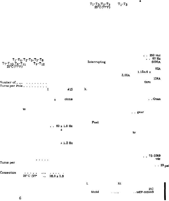
Resistance beween lead. . . 0.355± 0.036 ohms
pairs T1-T4, T2-T5, T3-T6
T7-TI0, T8-T11 and T9-T12
at 25°C (7T’F)
e. Generator Rotor.
DOD Drawing No . . . . . . . . . . . .
72-5230
Air Gap . . . . . . . . . . . . . .
.090 to .106
Number of Poles . . . . . . ... . ...4
Turns per Pole .11...... . . . . . .
262
Conductor . . . . . . . . . . . . 1 strand of #15
AWG magnet wire
Connection . . . . . . . . . . . . . . .
series
Resistance of Connected . . . 3,82 & ().38 ohms
Poles at 25° C (77° F)
f. Engine. Refer to Operator and
Maintenance Manual.
g. Exciter Assembly.
Frequency Regulation . . . . . .
Short Term Steady State . . . .
Stability (30 see)
Long Term Steady State . . . .
Stability (4 hrs)
Frequency Drift (8 Hr period) .
h. Exciter Stator.
i.
1-2
DOD Drawing No . . . . . . . . .
Number of Poles ... ...,,
Tmnsperc oil . . . . . . . . .
Conductor . . . . . . . . . . . .
Organizational
. . .
+ 1.2 Hz
. . .
± 1.8 Hz
. . .
+ 1.2Hz
. . .
72-5240
. . . . . . .
8
400
1 stand of #23
AWG magnet wire
Comection
series
Resistance at” 2&’”C” (~7; F) “ 1 1 “ ~6:0”*”3.6 ohms
Exciter Rotor.
DOD Drawing No. . . . . . . . . . . .
72-5220
Air Gap . . . . . . . . . . . . .
.052 to .064
Number of Slots . . . . . . . . . . . . ...36
Change b
Pitch of Coil . . . . . . . . . . . . . ...1-4
Coil Groups . . . . . . . . . . . . . . ...24
Coils per Group . . . . . . . . . . . . ...2-1
Turns per Coil . . . . . . . . . . . . ...11
Conductor . . . . . . . . . . . 1 strand of #17
AWG magnet wire
Resistance between . . . . . 0.677 + 0.068 ohms
T1-T2, T2-T3 and T1-T3
at 25°C (77°F)
j. Circuit Breaker.
DOD Drawing No. . . . . . . . . . . .
72-5173
Construction
Handle Spacers . . . . . . . . . . . aluminum
Handle Tie Bars . . . . . . . . . . aluminum
Mounting Insert . . . . . . . . . . . . . steel
Washer . . . . . . . . . . . .
external tooth
Studs . . . . . . . . . . brass with silver or
tin plated
Handle Tie Pin . . . , .
corrosion resistant
steel
Type . . . . . . . . . . . . . . . . .. relay trip
Voltage . . . . . . . . . . . . . . . ..250vac
Frequency . . . . . . . . . . . . . . . ..60Hz
[ntermpting Capacity . . . . . . . . . . . 5000A
Relay Coil . . . . . . . . . . . . . calibrated to
carry O. 82A
Trip . . . . . . . . . . . . .
1.13A 6+ 3 min
Trip . . . . , . . . . . 3.00A
instantaneously
Maximum Contact Capacity . . , . . . . . 104A
Temperature Range . . . . . . . 54” C thm 85° C
129° F thru 185° F
k. Engine Accessories.
(1) Fuel injection pump.
Manufacture r, . . . . . . . . . . . .. onan
Model . . . . . . . . . . . . . . . .147 -0263
Type . . . . . . . . . . PSU, single plunger
multi outlet
Drive Type . . . . . . . . . ..gear and cam
Mounting . . . . . . . . . . . block mounted
(2) Fuel transfer pumps. Refer to operator and
Organizational Maintenance Manual.
(3) Electric starter. Refer to Operator and
Organizational Maintenance Manual.
(4) Battery charging alternator. Refer to Operator
and Organizational Maintenance Manual.
(5) Fuel solenoid valve.
DOD Drawtng No . . . . . . . . . . ..72-5~9
volts . . . . . . . . . . . . . . . . .
24 vdc
Watts . . . . . . . . . . . . . . . . . .
12 w
Input Pressure . . . . . . . . . . . ..20 Pai ,
Orifice Size . . . . . . . . . . . . . 0.187 inch
(6) Oil pump.
1,
Type . . . . . . . . . . . . . . .
gear driven
Acoustic Suppression Kit.
Manufacturer . . . . . . . . . . . . . . . . . .
IAC
Model . . . . . . .. ME P . . . . . . . .. MEP-OO2AAS
Type . . . . . . . . . . . . . . . .
sound absorptive
cover