TM 9-6115-660-13&P
4-19 ACCESSORY BOX MAINTENANCE.
This task covers:
a. Removal
c. Installation
b. Repair
INITIAL SETUP
Tools
Materials/Parts - continued
Tool Kit, General Mechanic’s
Rivets, Blind
(item 1, appendix B)
Washers, Lock (item 1, appendix I)
1/4-inch Drill
(item 2, appendix B)
Equipment Conditions
Blind Hand Riveter
(item 5, appendix B)
Reference
Materials/Parts
Trailer handbrakes set, front support leg/land-
ing leg lowered, and rear leveling-support jack
Catch, Clamping and Strike
lowered; paragraph 2-3.2.1.
Hasp
Nuts, Self-locking
NOTE
Accessory box mounting hardware for PU-798A and PU-799A (plain nuts, lock washers,
flat washers, and cap screws) differs from that used on other power units, but removal
and installation procedures are similar.
REMOVAL
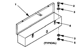
1. Release clamping catches (4, figure 4-19) and open accessory box cover (1).
Figure 4-19. Replace Accessory Box.
2. Remove accessories from accessory box.
3. Remove self-locking nuts (5), flat washers (3), machine bolts (2), and accessory box (1).
Change 2 4-39