ARMY TM 9-6115-464-34
AIR FORCE TO 35C2-3-445-2
NAVY NAVFAC P-8-624-34
3-7. SPEED SWITCH.
a. General.
(1)
(2)
(3)
(4)
(5)
The speed switch provides sequenced control of circuits during engine startup, and protection
against engine overspeed during operation. Three sets of contact elements, S9-1, S9-2, and S9-3,
contained in the speed switch, are set to open, close, or transfer at certain engine speeds. The
speed switch drive gear is designed to drive the speed switch at one-half engine speed.
At an engine speed of 580 to 620 rpm (accelerating) element S9-1 transfers two sets of contacts,
energizing the field flash circuit and de-energizing the crank relay to stop the starting motor.
On tactical precise sets, when the engine reaches the speed range of 1180 to 1220 rpm (50/60 Hz),
1650 to 1700 rpm (400 Hz), element S9-2 closes, energizing the electro–hydraulic governor which
takes over control of engine speed.
Speed switch element S9-3 consists of two sets of contacts which are set to transfer at an engine
speed of 2425 ± 25 rpm to shut down the engine and prevent damage to the equipment. Shutdown is
achieved by de-energizing the stop-run relay and the fuel solenoid, cutting off fuel to the engine.
Elements S9-1 and S9-2 reset at 100 rpm (decreasing) below actuation speed. Element S9-3 is
manually reset by a pushbutton on the speed switch housing.
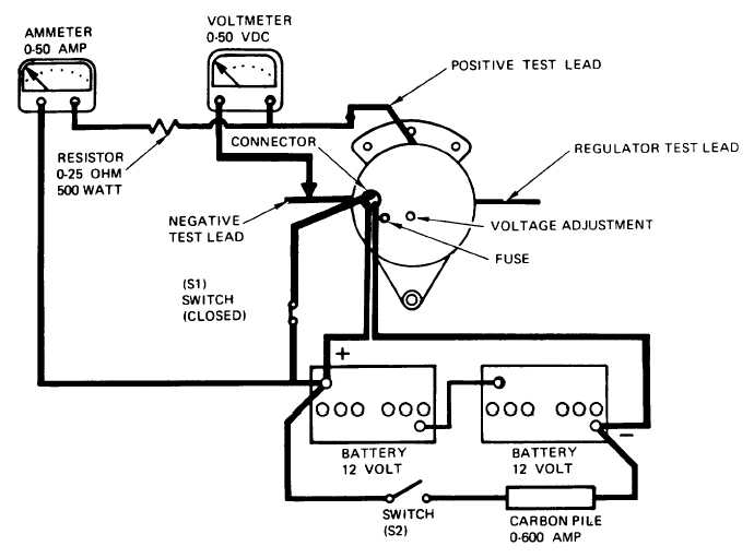
Figure 3-14. Output and Voltage Protector Test.
3-31