ARMY TM 9-6115-464-34
AIR FORCE 35C2-3-445-2
NAVY NAVFAC P-8-624-34
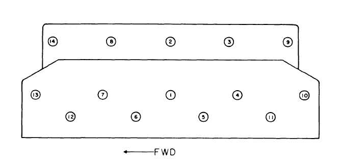
Figure 3-49. Cylinder Head Nut Tightening Sequence
3-55. CAMSHAFT
a. Removal.
(1) Remove oil pan (paragraph 3-37).
(2) Remove oil pump assembly (paragraph 3-38).
(3) Remove timing gear cover (paragraph 3-51).
(4) Remove rocker arm assembly and push rods (paragraph 3-54).
(5) Rotate engine crankshaft until screws (1, figure 3-50) are visible through holes in camshaft drive
gear.
(6) Refer to the Operator and Unit Maintenance Manual and remove the fuel filter assemblies.
NOTE
Rotate crankshaft as necessary to lift valve tappets. Use tapered wooden dowels or
magnets to hold tappets in topmost position.
(7) Remove screws (1) and Iockwashers (2) to remove camshaft (5).
(8) Remove valve tappets (35, figure 3-46).
3-116