
T.O. 35 C2-3-442-2
P-9-TM-457-35
TM 5-6115-457-34
TM-07464A-35
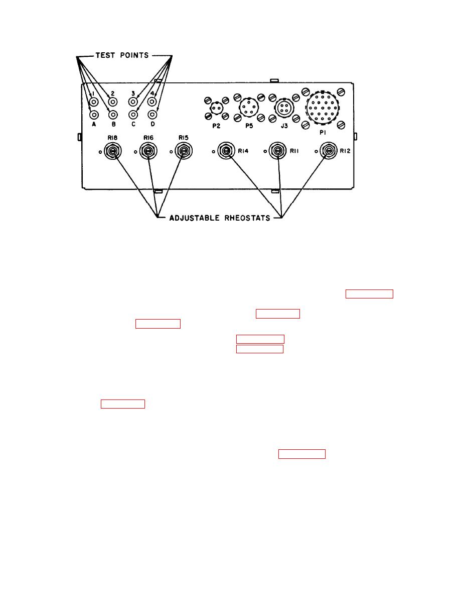
Figure 6-54. Precise governor control unit (A23) adjustments and test points.
gain (R16) as set for single unit operation
6-203. BENCH TEST.
are too high for parallel operation. The
a. Connect the governor control unit to
gain adjustments of both units should be
reduced the same amount. If the above
test equipment as illustrated in figure 6-55
adjustments do not eliminate the instability,
and perform test as specified in procedural
remove all connections and perform the
analysis table 6-21.
resistance checks listed in table 6-20.
NOTE
Readings which do not agree with the values
in the table indicate a malfunctioning com-
ponent in the control unit and it should be
the precise governor control unit
replaced,
schematic. Refer to the appro-
priate figure when checking indi-
b. Remove precise governor control
vidual components for required
unit from right hand side of lifting frame
values.
as follows: Refer figure 3-2.
b. Remove the precise governor control
1. Remove hinge cover from top of
unit from the test equipment.
unit by removing two screws.
6-204. DISASSEMBLY .
2. Tag and disconnect harness
a. Refer to figure 6-56 and disassem-
assembly.
ble the precise governor control unit to the
extent necessary to accomplish repair. Pay
3. Lift unit out of retainer.
particular attention to the following.
Change 3
6-164

