
TM 5-6115-400-35
terbore in the cylinder block (measure at
two or more locations). The specified
(c) If necessary, machine the bottom surface
depth is .460 inch-.462 inch.
of the sleeve flange to make it as true as
possible to a 900 angle with the sleeve
center line.
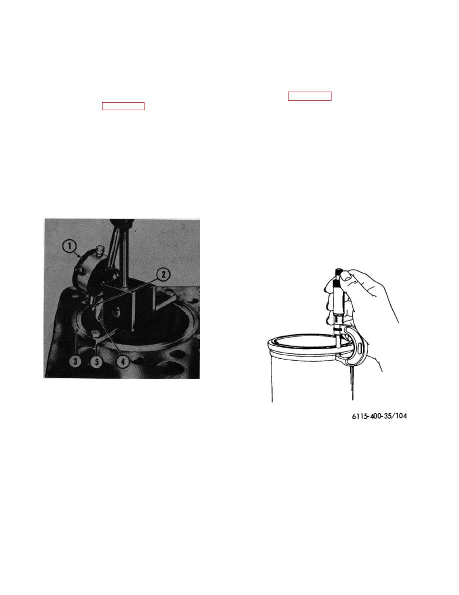
sleeve flange (measure at two or more
locations). The specified width is .463
out of the sleeve to allow the dial indicator
inch-.465 inch.
to contact the sleeve counterbore in the
(c) Subtract counterbore depth from width of
cylinder block. Drill and tap two holes in
the sleeve and attach a strap or bar as
cylinder sleeve flange.
shown.
The result is the cylinder ,sleeve standout.
(3) The protrusion (standout) of the cylinder
If the standout is not within the specified
sleeve flange above the top flat surface of the
.002 inch.005 inch, install a cylinder
cylinder block is very important. The specified
sleeve shim of the proper thickness in the
standout is .002 inch-.005 inch.
Measure
sleeve counterbore to bring the standout
cylinder sleeve standout as follows:
within the specified limits.
Cylinder
sleeve shims are available in .005 inch,
.008 inch, .010 inch, .015 inch and .020
of cylinder sleeve coun-
inch thickness.
If shimming will not
correct the cylinder sleeve standout,
reworking of the counterbore will be
necessary (refer to cylinder sleeve
reseating, para d).
1.
Dial indicator
2.
Indicator contact point
3.
Cylinder sleeve tool
4.
V-section (cut from sleeve)
5.
Mounting bar
6115-400-35/103
Figure 104. Measuring width of cylinder sleeve
flange.
Figure 103. Measuring out-of-8quare relationship of
cylinder sleeve counterbore.
139

